The automotive manufacturing industry has always run on precision. Every bracket, chassis rail, tube joint, piston ring, and airbag component that leaves a production line must meet exact dimensional specifications — consistently, across thousands of parts, shift after shift. For decades, conventional methods have handled this work. Plasma cutters, punch presses, mechanical saws, and manual marking systems were the default on shop floors at every tier of the supply chain.
But the production environment has changed — and conventional cutting has not kept pace.
Today’s automotive suppliers face a fundamentally different set of demands than they did ten or fifteen years ago. Batch sizes are shrinking as OEMs share platforms across model lines and demand greater production flexibility. Material variety has expanded dramatically, with high-strength steel, advanced aluminum alloys, carbon fiber composites, and EV-specific materials now sitting alongside traditional mild steel on the same production floor. Traceability requirements have moved from assembly-level to component-level, meaning every individual part needs a permanent, machine-readable identity from the moment it is produced. And delivery windows have compressed to the point where rework and secondary operations are no longer an acceptable part of the production plan.
Conventional cutting processes were not designed for this reality. Tooling wears and dimensional accuracy drifts over long production runs. Plasma and oxy-fuel cutting generate heat-affected zones that distort thin sheet metal and weaken the weld joints that follow. Deburring, grinding, and edge dressing add labor and time to processes that should not produce those defects in the first place. And the hard changeover costs of tooling-based processes make mixed-model, small-batch production economically painful.
Laser cutting, welding, and marking technologies address each of these problems directly — at the process level, not through workarounds.
This blog covers the complete picture. From chassis fabrication and tube cutting to airbag composite processing, piston ring marking, and 2D/3D component identification, each section explains where conventional methods fall short, what laser processing delivers instead, and which SLTL laser solution is the right fit for each production application.

The State of Automotive Manufacturing Today
Modern automotive production is not what it was ten years ago. Platform sharing across model lines, growing EV content, lightweight structural materials, and increasingly complex part geometries have fundamentally changed what the shop floor needs to deliver.
At the same time, OEM supply chain expectations have tightened. Tier-1 and tier-2 suppliers now face:
- Smaller batch sizes driven by mixed-model production and platform flexibility
- Tighter dimensional tolerances as safety systems and structural assemblies become more complex
- Mandatory traceability at the individual component level — not just at the assembly level
- New material types including high-strength steel, advanced aluminium alloys, composites, and EV-specific materials
- Faster delivery windows that leave no room for rework or secondary operations
Conventional cutting processes — punching, plasma, sawing, and mechanical shearing — were designed for a different era. They work well in high-volume, single-material, single-geometry environments. In today’s production reality, they are a structural constraint.
What Conventional Cutting Gets Wrong in Auto Part Production
Before understanding why laser wins, it helps to understand precisely where conventional methods fail. These are not abstract concerns — they show up as scrap rates, rework hours, line stoppages, and quality rejections on a daily basis.
Dimensional Accuracy Degrades Over Time
Every punch press, plasma cutter, and saw relies on physical tooling: dies, electrodes, blades. All physical tooling wears. As it wears, dimensional accuracy drifts — sometimes gradually, sometimes suddenly when a tool edge chips or an electrode tip erodes.
In a production run of 5,000 identical chassis brackets, the parts produced in hour one and hour eight may differ by 0.3–0.5 mm. On a non-critical component, that’s manageable. On a structural weld joint or a safety bracket, it’s a reject — or worse, a warranty claim down the line.
This is not an operator error. It is an inherent limitation of contact-based cutting tools operating under load and heat.
Heat-Affected Zones Compromise Material Integrity
Plasma cutting, oxy-fuel cutting, and even aggressive mechanical operations generate significant heat at the cut edge. This heat creates a heat-affected zone (HAZ) — a region where the base material’s microstructure changes, hardness alters, and internal stresses accumulate.
For high-strength steel used in chassis and structural components, HAZ can reduce the intended tensile strength of the cut edge. For thin-gauge aluminium used in body panels and EV battery enclosures, it causes warping and distortion that makes downstream assembly difficult or impossible without rework.
When these parts go on to be welded, the HAZ at the cut edge becomes the weakest link in the joint.
Secondary Operations Add Cost and Time
Mechanical punching almost always produces a burr on the cut edge. Plasma cutting leaves dross and edge roughness that requires grinding. These secondary operations — deburring, grinding, edge dressing — add labour cost, processing time, and variability to the production process.
In a lean manufacturing environment, secondary operations are pure waste. They add no value; they only remove a defect that should not have been introduced in the first place.
Changeover Costs Are Too High for Modern Batch Production
A conventional stamping or punching line set up for one part family requires significant retooling to switch to a different geometry — new dies, new fixtures, new qualification runs. In a world where batch sizes are shrinking and product variety is growing, this is an operational liability.
A tier-2 supplier producing 40 different bracket variants for three different vehicle platforms cannot afford to spend 6 hours retooling between batches.
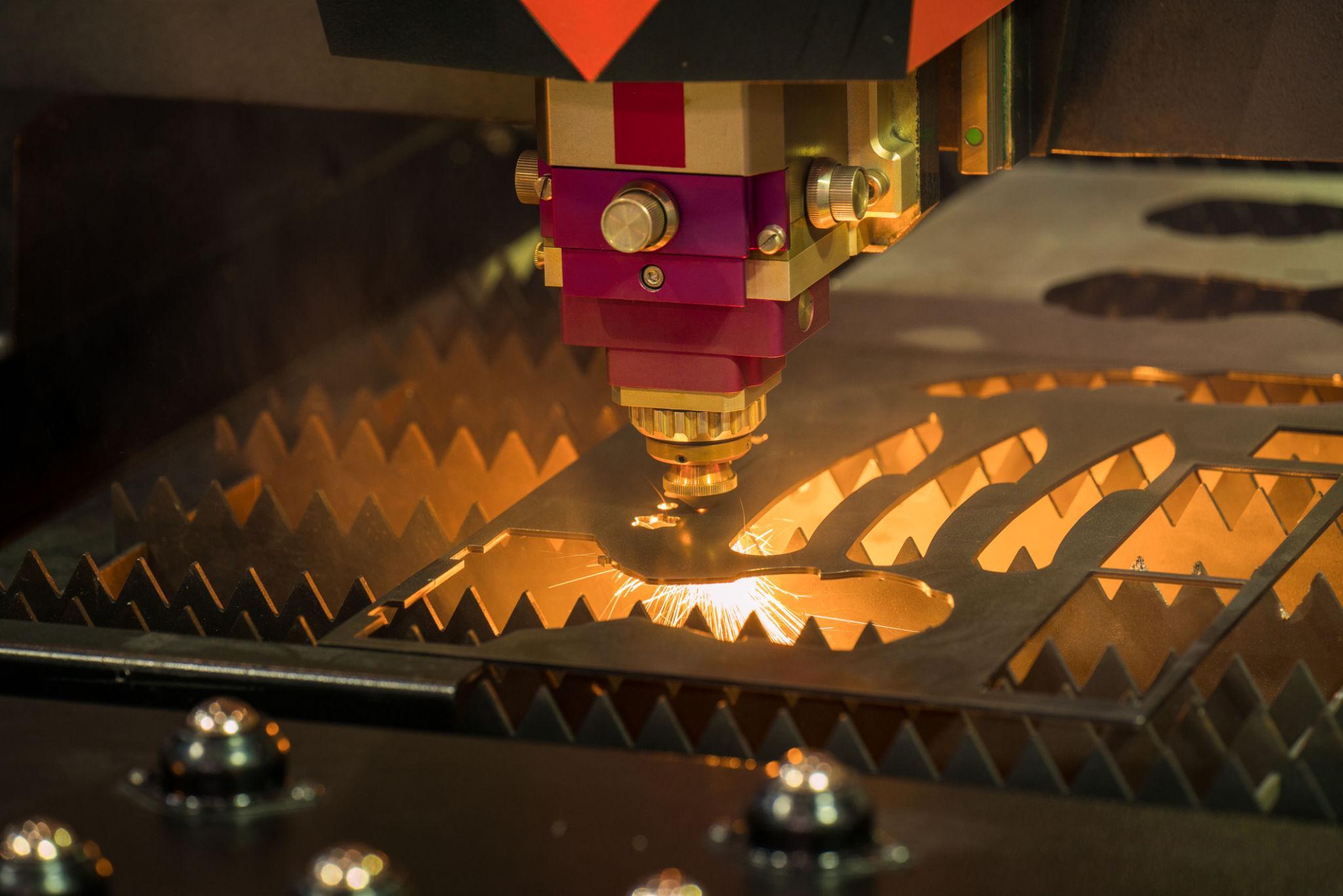
Why Laser Cutting Changes the Equation
A laser cutting machine for automotive parts solves each of these problems at the source — not through workarounds, but through a fundamentally different process architecture.

No Tooling, No Wear, No Drift
Laser cutting has no physical contact with the workpiece. The cutting action comes from a focused beam of coherent light — typically a fibre laser operating in the 1–20 kW range for automotive applications. There are no dies to wear, no electrodes to erode, no blades to resharpen.
The CNC programme that defines the cut geometry is the same on day one and day 1,000. Part number 10,000 is dimensionally identical to part number one. This is the most important advantage in high-volume automotive production: repeatable accuracy that does not degrade over time.
Positioning accuracy on modern fibre laser cutting machines is typically ±0.03–0.05 mm across the full working envelope. For reference, that is thinner than a human hair.
Minimal Heat-Affected Zone
The laser beam diameter at the workpiece surface is typically 0.1–0.3 mm. This tiny spot concentrates cutting energy precisely at the cut line, leaving the surrounding material largely unaffected. HAZ in optimized laser cutting is measured in fractions of a millimeter, compared to several millimeters in plasma cutting.
The practical result: less distortion on thin sheet, better edge condition for welding, and preserved material properties in high-strength steel. Downstream weld quality improves directly as a result.
Near-Burr-Free Edges — Eliminate Secondary Operations
When cutting parameters are properly optimised for the material and thickness, laser cutting produces a smooth, near-burr-free edge that requires no post-processing deburring or grinding on most automotive applications. The edge roughness (Ra) on an optimised laser cut is typically 3–6 µm — acceptable for direct welding without any edge preparation.
This eliminates an entire process step and all the labour, time, and variability that goes with it.
Sub-Minute Changeover Between Part Geometries
Switching between part programmes on a laser cutting machine takes less than 60 seconds — load the new CNC file, confirm parameters, begin cutting. There is no physical retooling. No new dies. No qualification run.
This makes laser cutting the natural technology for mixed-model production environments where batch sizes are small and variety is high. A supplier producing 40 bracket variants across three platforms can run them all on a single laser cutting machine, back to back, with negligible changeover cost.
Understanding which laser power level suits your specific mix of sheet thicknesses and tube sizes is an important specification decision — the detailed guide on How to Choose the Right Laser Power for Automotive Sheet and Tube Cutting walks through the material-power-speed relationship with production examples.
Application by Application: Where Laser Processing Delivers in Automotive
1. Chassis Cutting — Structural Accuracy Where It Matters Most
The chassis is the backbone of the vehicle. Every joint, bracket, and rail carries load — and the quality of every cut edge directly affects the quality of every weld joint. Poorly cut edges mean poor weld fit-up, which means weaker joints, more filler metal, more rework, and more variability in the finished assembly.
Fibre laser cutting machines in the 6–15 kW range deliver cut-edge quality on structural steel — 3 mm to 12 mm — that plasma simply cannot match. The edge is square, smooth, and ready to weld without grinding. Cut speed at this power level is also significantly faster than plasma on thin-to-medium gauge material.
The comparison between these two technologies deserves a closer look before any purchasing decision. The article Laser Cutting vs Plasma Cutting for Automotive Chassis Parts provides a direct side-by-side comparison of cut quality, edge condition, heat-affected zone, operating cost, and total cost of ownership across a typical chassis production scenario.
For manufacturers looking to specify a cutting platform for chassis work, Best Laser Cutting Machine for Chassis Cutting and Automotive Fabrication covers bed size, power range, automation options, and the specific features that matter for structural steel cutting.
Recommended SLTL Machine: Infinity F1 For heavy-duty chassis cutting — thick structural steel, high-volume production, demanding duty cycles — the Infinity F1 high-power laser cutting machine is purpose-built for this environment. It handles the material thicknesses and production intensities that chassis fabrication demands, without compromise.
2. Tube Laser Cutting — Frames, Exhaust Systems, and Roll Structures
Automotive frames, sub-frames, exhaust manifolds, roll cages, and structural cross-members are all tube-based. Cutting tube accurately — especially producing the compound bevel cuts, saddle notches, and coped ends needed for tight weld joint fit-up — is something conventional sawing and plasma absolutely cannot do reliably or economically.
A tube laser cutting machine processes round, square, rectangular, and custom profile sections, cutting end bevels, through-holes, slots, and saddle joints in a single automated pass. No secondary sawing. No manual fitting. The resulting joint geometry is accurate to within ±0.1 mm, which translates directly into tighter weld gaps and better-quality welds — with less filler and less distortion.
The specific advantages of tube laser cutting for frame and exhaust applications are explored in detail in How Tube Laser Cutting Supports Automotive Frames and Exhaust Parts. For procurement teams evaluating tube cutting platforms, Tube Laser Cutting Machine for Automotive Part Suppliers covers bore range, axis count, chuck capacity, and the specification criteria that matter for automotive tube work.
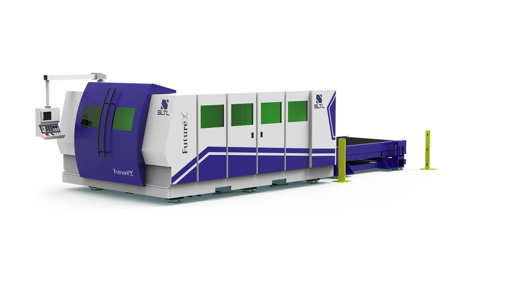
Recommended SLTL Machine: Future X The Future X is SLTL’s most advanced laser solution, equipped with all the features needed to give manufacturers a genuine competitive edge in tube and complex-profile cutting. Its advanced capabilities make it the right choice for suppliers who need to handle complex joint geometries and tight delivery schedules simultaneously.
3. Sheet Metal Cutting — Body Panels, Brackets, and Reinforcements
Body-in-white components — door inners, floor pans, A-pillar gussets, reinforcement brackets, hinge plates — cover a wide thickness range from 0.8 mm exterior skin panels to 6 mm structural reinforcements. A single laser cutting platform handles this entire range with a parameter change, not a tooling change.
The key specification decision here is laser power — too low, and thick sections cut slowly; too high, and thin material risks blow-through or excessive HAZ. The practical guide to How to Choose the Right Laser Power for Automotive Sheet and Tube Cutting explains how to match power to your specific material and thickness mix.
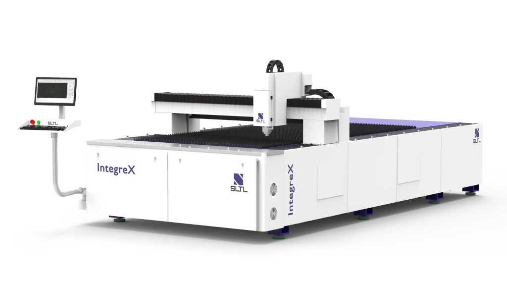
Recommended SLTL Machine: IntegreX For manufacturers who need to increase sheet metal cutting productivity and efficiency without the capital cost of a top-tier machine, the IntegreX is SLTL’s most affordable laser cutting solution. It delivers genuine production capability on automotive sheet metal thicknesses while keeping acquisition and operating costs accessible for tier-2 and tier-3 suppliers.
4. 3D Laser Cutting — Complex Geometries and Formed Parts
Not all automotive cutting happens on flat sheet. Hydroformed body panels, deep-drawn structural components, and complex stamped assemblies need to be trimmed and pierced after forming — in three dimensions, on curved surfaces, at compound angles.
Conventional tooling-based trimming of 3D formed parts requires expensive hard tools specific to each part geometry. Every design change means new tooling. Lead times are long and tooling costs are high.
3D laser cutting replaces this entire tooling-based process with a digitally programmed laser head that follows the three-dimensional surface of the part. Design changes require a programme update, not new hard tooling. Prototyping and low-volume production become practical without tooling investment.
Recommended SLTL Machine: X5 The X5 is SLTL’s dedicated 3D laser cutting machine, specifically designed for complex three-dimensional cutting on formed automotive components. It handles the compound surface geometries and cutting angles that flat-bed systems simply cannot reach.
5. Airbag and Composite Material Cutting — Where Contact Cutting Fails
Airbag fabric, carbon fibre reinforced polymer (CFRP), Kevlar composites, and the specialist films used in automotive interior and safety systems are a category of their own. Mechanical contact cutting — blades, routers, punches — frays woven fibres, delaminate composite layers, leaves edge contamination from tool material, and creates thermal damage at cut edges from tool friction.
Laser cutting is contactless. There is no blade pressure, no tool wear, and no edge delamination. The cut is defined entirely by the digital programme and the focused beam. Edge quality on composites is clean, consistent, and repeatable — batch after batch, without tool degradation.
For safety-critical materials like airbag fabric — where a frayed edge or delaminated cut is a direct product safety risk — contactless laser processing is not a preference, it is a requirement. The full technical argument is laid out in Why Airbag and Composite Material Cutting Needs Contactless Laser Processing.

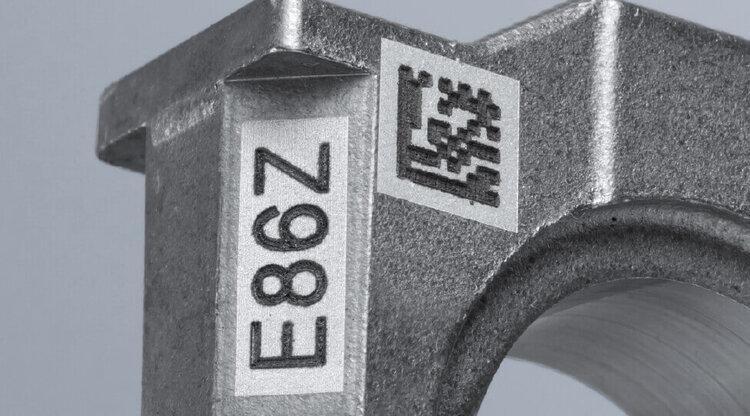
6. Piston Ring Laser Marking — Traceability at Component Level
Piston rings are a high-precision, high-volume component operating in one of the most demanding environments in the engine — high temperature, high pressure, continuous chemical exposure. Traceability marking on piston rings has to survive all of it.
Conventional marking methods fall short here. Dot-peen marking creates mechanical stress on thin ring sections. Inkjet marking uses consumables and produces marks that do not survive engine operating conditions. Neither method reliably produces the machine-readable DataMatrix codes that modern OEM traceability requirements demand.
Laser marking produces permanent, high-contrast DataMatrix codes, part numbers, and batch identifiers directly in the ring material — no consumables, no mechanical contact, no marks that fade or wash off. The mark is formed by a controlled change in the surface microstructure, and it survives honing fluid, combustion temperatures, and engine oil chemistry without degradation.
For anyone processing piston rings, What Is Piston Ring Laser Marking and Why Does It Matter? is essential reading — it covers the metallurgical basis of the process, traceability requirements, and the marking parameters that matter for different ring materials. Procurement teams can use the Laser Marking Machine for Piston Ring Manufacturers: Buyer Guide to specify the right system for their production volume and traceability requirements.
7. Laser Marking for 2D and 3D Automotive Components
Piston rings are one application, but automotive laser marking spans a much wider range of components — connecting rods, camshafts, cylinder bores, cast housings, aluminium structural parts, and every bracket and bracket variant that moves through a modern supply chain.
The marking application divides into two technical categories: 2D marking for flat or gently curved surfaces, and 3D marking for complex curved surfaces where a flat focal plane cannot maintain consistent beam focus and power density across the part.
Understanding which capability you need — and what to look for in the equipment that delivers it — is the subject of 2D and 3D Laser Marking for Automotive Components: What to Check Before Buying.

A related decision is mark appearance: for stainless steel components, laser oxidation can produce full-colour marks for anti-counterfeit, branding, or visual differentiation purposes. For most traceability applications on carbon steel and aluminium, high-contrast black or white annealing marks are the standard. The comparison in Color Marking vs Black and White Marking for Automotive Parts explains which process suits which substrate and application.
For high-throughput inline marking — components arriving on conveyors in production fixtures — the SPM Laser Marking Machine from SLTL is designed for exactly this integration scenario. The overview in SPM Laser Marking Machine for 2D and 3D Automotive Jobs covers the integration requirements, marking speed, and configuration options for production-line deployment.
The Role of Laser Welding in Automotive Part Production
Cutting is the beginning of the process, not the end. Once parts are dimensionally accurate and edge-ready, they need to be joined — and the same precision that laser cutting brings to raw material processing, laser welding brings to assembly.
Automotive laser welding produces narrow, deep weld beads with very low heat input compared to MIG or TIG welding. For thin-walled assemblies — EV battery enclosures, heat exchanger plates, sensor housings, lightweight structural members — this low heat input is the only practical way to join parts without distorting the assembly.
The physics of why laser welding reduces distortion, and the specific automotive assemblies where this matters most, are covered in How Laser Welding Reduces Distortion in Automotive Assemblies. The broader case for weld strength — including joint strength data and the applications where laser welding genuinely outperforms arc-based processes — is the subject of How Laser Welding Helps Automotive Suppliers Make Stronger Parts.
For EV and hybrid component manufacturers specifically, battery enclosure sealing, busbar welding, and cooling plate joining all have requirements that conventional arc welding cannot meet reliably. The Laser Welding Machine for EV and Automotive Component Manufacturers guide covers the power range, beam delivery options, and process monitoring features relevant to battery and drivetrain assembly welding.
The Total Cost Argument: Laser vs Conventional
The most common reason automotive suppliers hesitate on laser adoption is capital cost. A fibre laser cutting machine costs more upfront than a punch press or a plasma table. This is a real consideration — and it deserves an honest answer.
The capital cost comparison, however, is not the right comparison. The right comparison is total cost of ownership across a production horizon of 3–5 years. When all cost factors are included, the picture changes significantly:
| Cost Category | Conventional | Laser |
| Tooling (dies, punches, electrodes) | High — per-part tooling required | None |
| Consumables (blades, electrodes, tips) | Ongoing, significant | Low (nozzles, lenses) |
| Secondary ops (deburring, grinding) | Common — multiple parts per shift | Rare to none |
| Scrap and rework | 2–5% typical | Under 0.5% typical |
| Changeover time | 2–8 hours per tooling change | Under 5 minutes |
| Operator dependency | High | Low — CNC controlled |
| Material flexibility | Low — tooling is material-specific | High — parameter change only |
| Traceability integration | Limited | Full — direct part marking |
For most automotive suppliers running multi-material, mixed-part production at medium-to-high volumes, the payback period on laser capital investment — measured against saved tooling, scrap, secondary operations, and labour — falls between 18 and 36 months. High-volume single-material lines can achieve payback faster. Low-volume custom work justifies laser on flexibility and tooling savings alone, even at modest volumes.
SLTL Laser Solutions for Automotive Manufacturers
SLTL Group provides a complete ecosystem of laser processing solutions purpose-built for automotive production environments — from flat sheet cutting and tube processing to component marking and precision welding.
Future X — Advanced Laser Cutting Machine
SLTL’s most advanced laser cutting solution, equipped with every modern feature to give manufacturers a competitive edge in precision cutting. The Future X is the right choice for suppliers who need maximum capability in complex geometries, demanding duty cycles, and tight tolerance requirements. It sets the benchmark for what an advanced laser cutting machine can deliver on the automotive shop floor.
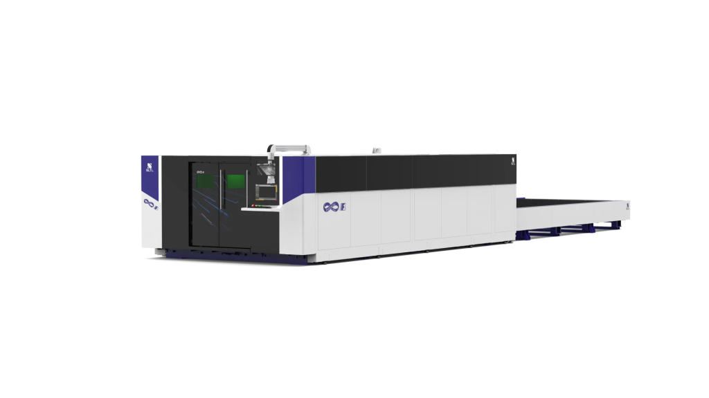
Infinity F1 — High Power Laser Cutting Machine
Built for heavy-duty manufacturing, the Infinity F1 handles the thick structural steel and high-volume production demands of chassis fabrication and heavy structural component cutting. When the job calls for sustained high-power cutting without compromise, the Infinity F1 delivers.
IntegreX — Affordable Laser Cutting Machine
The IntegreX is SLTL’s answer for manufacturers who need to increase productivity and cutting efficiency without maximum capital outlay. It is the most affordable entry point into fibre laser cutting without sacrificing the production capability that automotive part suppliers require. Ideal for tier-2 and tier-3 suppliers processing standard automotive sheet thicknesses.
X5 — 3D Laser Cutting Machine
Specialised for three-dimensional cutting on formed and complex-geometry automotive parts, the X5 handles compound surface cutting that flat-bed machines cannot reach. It is the right tool for trimming hydroformed panels, piercing deep-drawn components, and processing any automotive part where cutting happens on a curved or compound surface.

Laser Welding Machines
SLTL’s laser welding range covers both continuous-wave and pulsed configurations for automotive assembly applications, including remote welding heads for high-speed body-in-white work and precision welding stations for EV battery and drivetrain components.
Laser Marking Machines
Fibre and MOPA laser marking systems for part identification, DataMatrix coding, serial number marking, and traceability applications across all metal substrates. Available as standalone operator stations or as SPM-integrated inline systems for production-line deployment.
Frequently Asked Questions
Q1: What makes a laser cutting machine better than plasma for automotive parts?
Laser cutting produces significantly better cut-edge quality — lower roughness, smaller heat-affected zone, and near-burr-free edges — than plasma. It is also faster on thin-to-medium gauge material, requires no post-cut grinding, and holds tighter dimensional tolerances. The operating cost difference narrows at very high power, but quality and precision consistently favour laser across most automotive applications.
Q2: Can one laser cutting machine handle both flat sheet and tube cutting?
Some machines include tube cutting attachments that handle basic round and square profiles alongside flat sheet work. For serious tube cutting — complex joint geometries, multiple profile types, high volumes — a dedicated tube laser cutting machine with a full rotary axis and multi-chuck system is more appropriate.
Q3: Is laser marking permanent enough to survive engine operating conditions?
Yes. Laser marks are formed by a permanent change in the surface microstructure of the metal — not by surface coatings or inks. They survive engine temperatures, lubricant exposure, honing fluids, and pressure washing. DataMatrix codes on piston rings are routinely scanned successfully after extensive engine operating hours.
Q4: What is the difference between 2D and 3D laser marking for automotive components?
2D marking uses a fixed focal plane — suitable for flat or gently curved surfaces. 3D marking dynamically adjusts beam focus using a motorised Z-axis or variable focus lens to maintain consistent spot quality across highly curved surfaces like cylinder bores, cast housings, or complex structural castings.
Q5: How quickly can a laser cutting machine switch between different part programmes?
Programme changeover on a CNC laser cutting system takes under 60 seconds — load the new part file, confirm cutting parameters, and begin production. Physical setup changes (nozzle size, fixture) may add 5–15 minutes depending on the application, but there is no hard tooling to swap or re-qualify.
SLTL Group — Laser Cutting, Welding and Marking Solutions for Automotive Manufacturing Contact SLTL to discuss your application, request a sample cut, or explore the right machine for your production environment. Explore SLTL Laser Solutions